
The design of cold-formed light gauge steel members isn't straightforward. Accounting for local, distortional and lateral torsional buckling modes of failure significantly complicates design expressions, which in themselves are at best approximations to actual behaviour. The designers' ‘feel’ for behaviour tends to get lost in the mathematics. . .
Traditionally, Standards such as AS/NZS 4600 have utilised the so-called ‘effective width method’ (EWM) as the basis for developing behavioural models.
The EWM has its foundation in observed behaviour in that when thin plate elements locally buckle, the central portion sheds load significantly while the stiffer edge/corner areas accept greater load. Hence the conceptual model assumes only a certain width of each plate is effective in accepting load, with the remainder discarded.
While this model works reasonably for single plates and simple member cross sections, for more complicated members with longitudinal stiffeners rolled in and interaction between local, distortional and overall buckling, increasingly more complex equations need to be configured to approximate reality.
Image courtesy of University of Sydney
.png?variant=HalfWidth)
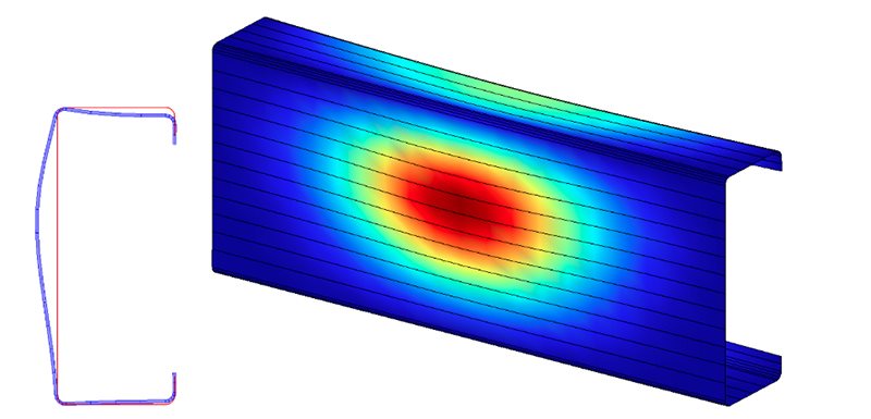
Local buckling of lipped channel section. Courtesy University of Sydney.
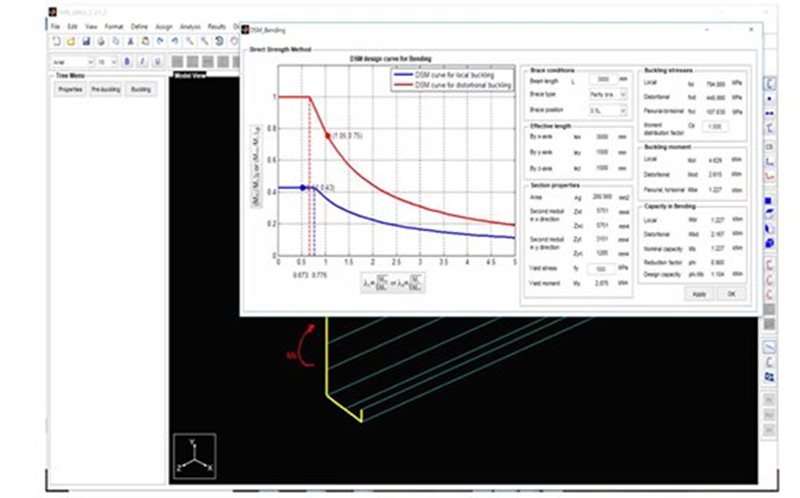
Recognising the increasing limitations of the EWM and the increasing computational power we have with computers, recent best practice is shifting towards adoption of the Direct Strength Method (DSM). For example, in the latest 2018 revision of AS/NZS 4600, the DSM has become a primary focus, with the EWM effectively grandfathered. The DSM has been made freestanding in Section 7 and Appendix D of AS/NZS 4600 to simplify design.
The DSM of design is a new method that accounts for the behaviour of complete cold-formed thin-walled sections including longitudinal stiffeners rolled into the sections. The 2018 revision of AS/NZS 4600 includes new application to sections with holes, fire design, shear and beam-columns and extensive expansion of the range of prequalified members applicable to the DSM.
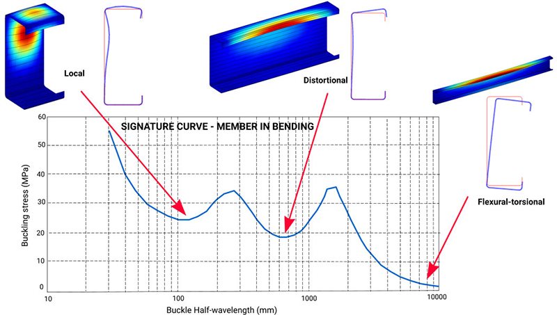
The DSM relies on the ability to compute the buckling stresses of thin-walled sections. The finite strip method (FSM) of analysis may be used to provide the so-called ‘signature curve’ of the member, which indicates member buckling stress as a function of member length. Shorter members display local buckling modes. As the length increases, distortional then flexural torsional modes of buckling come into play to limit the member strength. The buckling stresses derived from the FSM analysis are used in the simple DSM design equations.
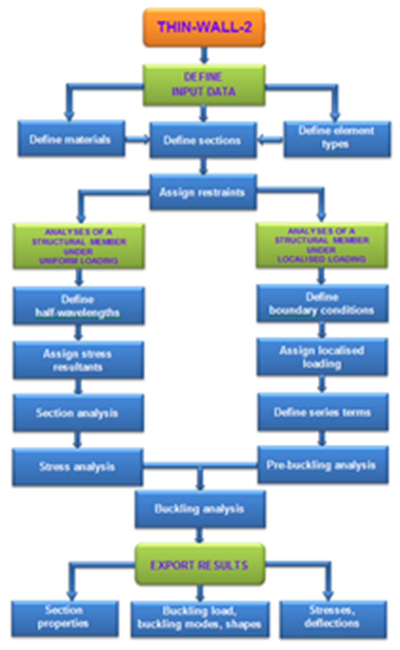
With the inclusion of shear design in the DSM, new FSM software THIN-WALL-2 (Nguyen, Hancock and Pham, 2015) has been developed at the University of Sydney to allow easy DSM design for compression, bending and shear for a range of sections.
Thin Wall 2 details (PDF)