The Falcon Street Pedestrian Bridge is a curved, continuous steel box girder structure that allows unimpeded access for pedestrians and cyclists across 19 lanes of the Warringah Freeway north of the Sydney Harbour Bridge.
Client
Architect
Structural Engineer
Head Building Contractor
Steel Fabricators
Steel Detailer
Coatings Supplier
Metal Building Contractor
The Falcon Street Pedestrian Bridge on Sydney’s lower north shore comprises just five spans installed as a 193m-long structure. It was built to minimise disruption to traffic over 19 lanes of the Warringah Freeway.
The project involved extensive stakeholder consultation to determine the best location and alignment to suit community needs. The specific site constraints dictated a continuous long-span steel box girder structure, curved both in plan and elevation as the best solution.
After an extensive review of options a trapezoidal steel box girder option was selected by the project stakeholders based on the following criteria:
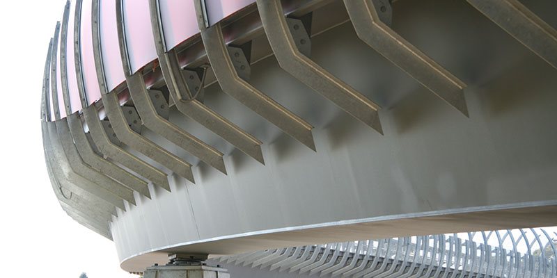
The superstructure is a 1500mm-deep fully welded trapezoidal orthotropic steel box girder. The deck slab has an anti-skid corrosion protection coating that accommodates pedestrian and cyclist traffic across the bridge. Provision was made in the design for the installation of Tuned Mass Dampers (TMDs) to negate dynamic effects due to the slenderness of the bridge structure. Minimising the overall structural depth was a key design consideration to meet the project constraints.
.jpg?variant=HalfWidth)
By minimising the overall depth of the structure and producing a slender structure with a span-to-depth ratio of 43, the design is cost-effective and minimises the quantity of steel required. The bottom flange of the box girder varies in thickness over the length from 16mm to 36mm, while the top flange remains a constant 20mm over the entire length of the bridge to carry the pedestrian traffic and did not require transverse or longitudinal stiffeners, thus significantly reducing the cost.
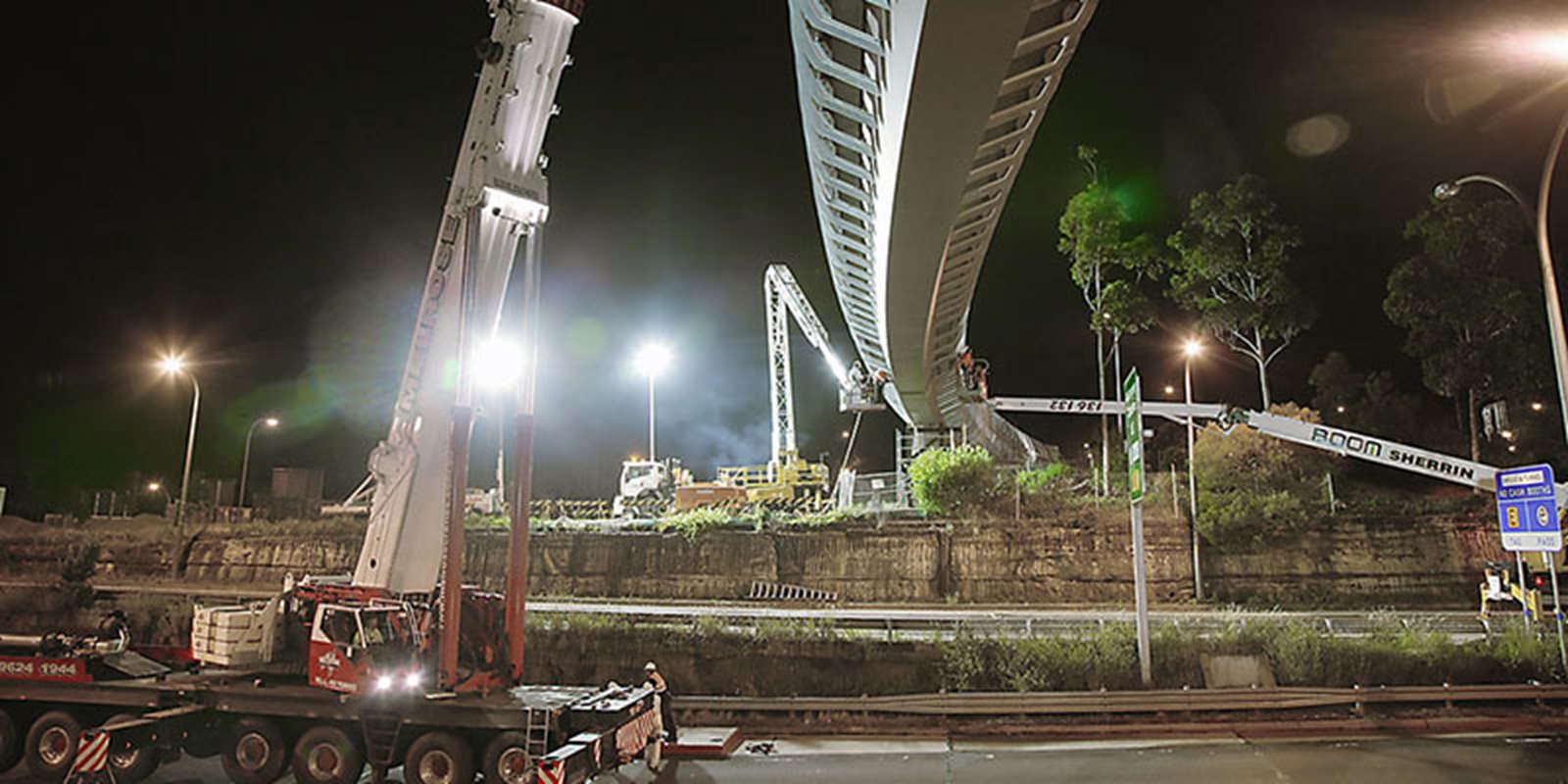
Each girder segment was designed to be lifted into place as a complete unit with all balustrades and anti-throw screens secured prior to lifting into position. Minimal works were therefore required to complete the bridge over live traffic.
Welded and bolted connections were carefully detailed to maximise efficiency and minimise cost. Each splice connection between the girder segments was bolted. The design allowed the splice joint to be completed during the scheduled road closures, which reduced the safety risks and cost.
The configuration of the Warringah Freeway was the key consideration in the erection sequence developed during the design phase. The steel superstructure was placed in six separate segments commencing from each abutment with an infill span completing the bridge. In consultation with the construction team and steel fabricator a number of features were designed and accommodated into the box girder to facilitate the completion of the bridge. These features included:
A top flange plate connection was designed at the splice points so that once the first girder segment had been placed, the next girder could then rest on the end of the first girder while the bolts within the splice joint were being torqued up. This enabled the crane to be demobilised before the bolted splice joint was fully completed. This connection modification reduced the risk of exceeding time limits for the road closures and provided a safer method of completing the splice connection.
A web connection was used instead of a bottom flange to provide a more cost-effective weld detail which still maintained clean lines along the bottom flange to meet architectural requirements.
Providing a shallow steel box girder was key to meeting the client’s architectural requirements as well as the site constraints. The bridge crosses two new off-ramps from the adjacent Falcon Street road bridge where the minimum vertical clearance of 5.4m needed to be provided. Coupled with minimising the vertical grades on the bridge to meet with the access and mobility code requirements, a structural depth of 1.5m was adopted.
For slender structures, dynamic performance is critical to functionality. For this bridge, dynamics were identified in the dynamic requirements of the Australian Bridge Code. Instead of design stage as a potential issue, although the design satisfied the length while maintaining the aesthetics of the superstructure. increasing the depth of the structure, thus increasing the costs, and compromising on the aesthetics, provision was made in the design for TMDs to be installed after the bridge was constructed.
This proved to be a more efficient design method compared with increasing the depth of the girder and it also fulfilled the project constraints. This provided a cost saving for the client by minimising the amount of steel required over the entire bridge.
The bottom flange of the box girder varies in thickness over the length of the bridge. The transition between flanges was detailed such to provide a clean line along the soffit of the bridge with the change in thickness being accommodated on the inside of the box girder. This met the aesthetic requirements and allowed the overall cost of materials to be reduced by providing an efficient design.
The welded and bolted connections were carefully detailed to maximise efficiency, minimise cost and enhance the safety of the construction method to complete the bridge. In addition, finite element analysis methods were adopted for the design of the diaphragms to optimise the plate sizes and confirm the design stress flows from the girder webs to the bearings.