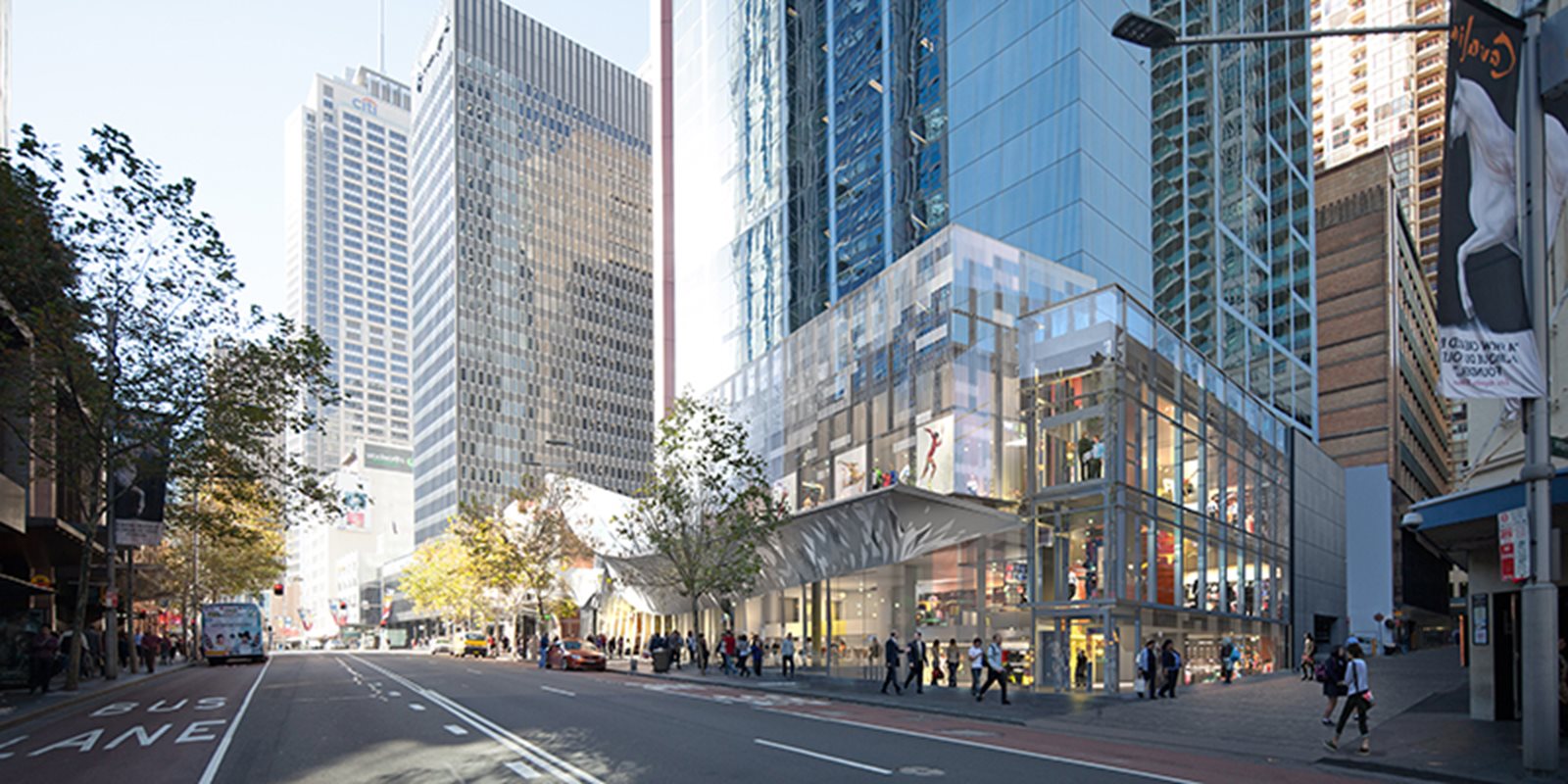
The entry awning at 580 George Street in the Sydney CBD provides natural light and air into the building while impressing with its striking free-form shape.
Architect
Structural Engineer
Head Building Contractor
Steel Fabricator
Steel Detailer
Coatings Supplier
Metal Building Contractor
Located on the corner of George and Bathurst Streets in the Sydney CBD, the redevelopment of 580 George Street has transformed the existing Art Deco-styled 33-storey commercial tower building.
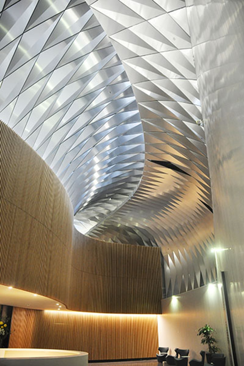
This contemporary upgrade consists of a new commercial lobby, retail spaces and a contemporary faҫade. Project architect fjmt’s approach was to develop an aspirational response that seeks to deliver an outcome beyond the mere functional to one that provides an engaging and vibrant statement. The design of the new lobby incorporates a dramatic metal awning inspired by the art of origami and engineered with the latest technology.
This geometrically structured self-supporting glass awning allows natural light and air into the building, provides greater shelter for pedestrians and offers an exciting structural facade to the city precinct. 580 George Street maximises amenity and improves the relationship between the building and streetscape by better defining and activating the building edge.
Cladding a free-form shape is always challenging. This project demonstrates an innovative and visually striking approach at the forefront of architectural design and engineering schematic solutions.
.jpg?variant=HalfWidth)
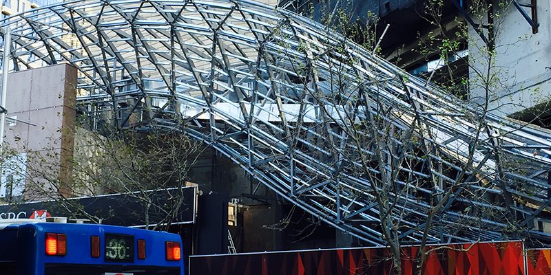
Key to the aesthetics of the design of the awning is a series of free-form curved surfaces with folded diamond-shaped metal panels. The faҫade surfaces are supported by a lightweight steel space frame that closely follows the design shape. The frame is clad with plywood and the diamond shaped panels.
Critical to the project was the need for close collaboration between the architectural form, the structural design and fabrication. The use of modern 3D software with additional bespoke development allowed the form to be optimised with minimal impact on other collaborators.
Using steel allowed for a light, high-strength structure that could efficiently utilise available space within the faҫade envelope. The predominantly bolted steel structure was fast to erect and provided a geometrically accurate base for the facade.
The precision of modern fabrication techniques enabled the complex geometric form to be simply erected with high accuracy.
The steel structure used 450 Grade square and rectangular hollow steel sections. The higher material strength and the improved buckling and torsion strength offered by these sections allowed the total steel quantity to be reduced.
The canopy is built onto the base of the existing building and can be readily dismantled and the materials recycled.
At all stages the 3D model of the architect, engineer and faҫade engineer progressed together. The space required between the structure and the cladding was critical and was often minimal.
The curved profile of the structure meant that every steel member and every connection was different. The structure, however, was typologically repetitious. That is, many members were similar but differed only in length and orientation of end cleats. This provided for efficient fabrication and erection through repetition, with the geometric variation easily handled by modern steel detailing and fabrication process.
The design standardised member sizes as much as practical. Square and rectangular hollow sections were used for their higher compression capacity and torsional stiffness.
The trusses comprised vertical planar welded frames running perpendicular to the axis of the awning or ceiling. These set the basic cross-section geometry of the structure. Each frame was planar with sections aligned to the plane of the frame. This allowed the frames to be easily set-out for accurate shop welding. The frames varied significantly in size but each was topologically similar. Smaller frames were fully welded and delivered to site. Larger frames were delivered to site in segments and site-welded prior to erection.
Section sizes were chosen so smaller sections were welded to larger ones, allowing lower cost fillet welds to be used where possible.
The frames were joined with SHS diagonals, each with slotted end plate connections, allowing site bolting. Additional site welding strengthened a small number of highly loaded connections. This allowed a consistent connection detail to be used throughout.